RF Geo Location Guide
RF Geo-location guide for Tourists
Circuit Diagram:

Output:

Theme parks, national parks, and other general large tourist attractions need directional guides to tell visitors where they are in the region. Especially existing technologies, distinctly such as GPS, cannot be reprogrammed to alter the area of interest. Furthermore, GPS technology can be on the whole used by anybody, actually making it insecure.
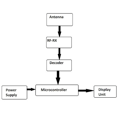
To address this issue, a park guidance system that exceptionally uses RF technologies to wirelessly guide users about their current position. RF based geolocation guide is a module where it is in general used to locate yourself in big confined spaces. This appears to be a very useful and practical method of guiding visitors in the park or in any secured areas where GPS probing is not allowed. This device aims to replace "you are here" signs that can be seen in those parks or secured areas. To build this module, we require RF transmitters, one receiver module. To detect the tourist, our machine employs an RF receiver circuit. The circuit can be carried by the tourist. The system then consists of RF transmitters strategically positioned in the park.
For example, if a park owner, wants the tourists to locate themselves in the park at five different locations, the park owner essentially has to set up these five RF transmitters at five different locations where he wants tourists to locate themselves and for every tourist, at the entry of the park, should be given a receiver module where it distinctly contains an RF receiver, a display, battery to generally run the components and a chip which elementally coordinates with display and receiver. The chip will be preloaded with the already placed RF transmitters frequencies so that it can, in most cases, detect the respective frequency only and display the corresponding location. When a tourist enters the park and reaches in range of any RF transmitter then, the receiver detects the RF and compares the frequency with the preloaded frequencies and if any frequency matches, then the corresponding location will be certainly displayed in the receiver module display. Like this, whenever the tourist enters the range of any RF transmitter, the receiver detects the RF and compares and shows the corresponding location.
RF technology is also used in a variety of applications. Personal identity applications, for example, are used to give authentication and permission to people who wear RFID tags so that they can be automatically detected by a central device. Another example is RFID tags that chiefly look like cards which are used as kind of smart cards, in fact, public transportation: when a cardholder presents the card in front of a scanner while boarding from a transporter, information on money deposited in the tag is immediately deducted. Particularly other uses for RFID tags, in general, include book markings for more really effective library administration, shipping containers for retail industry monitoring, and so on.
Working:
The input for this project comes
from a logic-state device, where '1' denotes high and '0' denotes low. This
logic-state input is interpreted as binary, with D6 being MSB and D9 being LSB.
So, when a binary sequence is supplied, the encoder transmits the bit sequence
through the RF transmitter, the RF receiver records the bit sequence, and the
relevant LEDs are shown as a result, being
D1 as LSB and D4 as MSB in the LED array. These output voltages are then
sent to the Arduino UNO. The input will be processed by Arduino, and the
relevant location will be shown based on the LED commands given in the Arduino.
The encoder will send the bit sequence thrice in this process, for error
detection, so that when the decoder gets bit sequences, these three will be
compared and the output will be delivered only if the three sequences are the
same.
Tools Used:
Software Tools: Proteus Professional 8.0, Arduino Integrated Development Environment (IDE)
Hardware Tools: M145026 (Encoder), M145027 (Decoder), Arduino UNO, RF Transmitter module, RF Receiver Module, LCD Display (16×2), Light Emitting Diode (LED), Resistor, Capacitor.
Flow Charts:
Transmitter side:
Receiver Side:
Arduino Code:
#include <LiquidCrystal.h>
LiquidCrystal lcd(12,11,5,4,3,2);
int A,B,C,D,RES;
void setup() {
lcd.begin(16,2);
lcd.setCursor(0,0);
lcd.print("LOCATION");
pinMode(10,INPUT);
pinMode(9,INPUT);
pinMode(8,INPUT);
pinMode(7,INPUT); }
void loop() {
RES = 0;
A = digitalRead(10);
B = digitalRead(9);
C = digitalRead(8);
D = digitalRead(7);
RES = A + (B*2) +(C*4) + (D*8);
if(RES <= 9) {
lcd.setCursor(0,1);
lcd.print("0");
lcd.setCursor(1,1);
lcd.print(RES); }
else {
lcd.setCursor(0,1);
lcd.print(RES); } }
For Block Diagrams of Encoder and Decoder, Please visit these pages:
Comments
Post a Comment